Home
/ Timer And Contactor R Relay Diagram / 8 pin timer relay wiring diagram in urdu/hindi | star delta timer connection in this video i practically explained the time relay.
Timer And Contactor R Relay Diagram / 8 pin timer relay wiring diagram in urdu/hindi | star delta timer connection in this video i practically explained the time relay.
Once the timer reaches the set timing, it stops and the contact closes thereby completing the circuit and. Timer and contactor r relay diagram / 3 phase motor wiring engineering electrical diagram contactor and timer. What is the main difference between mcb, contactor and overload relay as all the three are used to protect the electrical circuit? Cad file (on traceparts) for re22r2mmu: It has multiple transistors and relay outputs.
Contactors vs Relays | Mr. Electric of Dallas from www.mrelectricdallas.com The following is a timing diagram of this relay contact's operation: 23.03.2021 · timer and contactor r relay diagram ~ siemens overload relay wiring diagram | free wiring diagram. Thus relay will be on for required amount of time set by the user using pot and then it is. For all series specific instructions, accessories, and dimensions, see the individual series section. Figure 3.9 timing diagram 400a (electrically held). Conventional hardwiring to pushbuttons, selector switches, pilot devices and contactors can now be digital outputs r = relay t = transistor. Contactor switching time is higher than relay. Thus relay will be on for required amount of time set by the.
All type r relays with a manual operator must be used on circuits of the same polarity.
All type r relays with a manual operator must be used on circuits of the same polarity. It has multiple transistors and relay outputs. How to contactor with timer wiring diagram and partical. Once the timer reaches the set timing, it stops and the contact closes thereby completing the circuit and. Figure 3.9 timing diagram 400a (electrically held).
A relay is an electrically operated switch. It consists of a set of input terminals for a single or multiple control signals, and a set of operating contact terminals. Class 9999 type xtd and xte. Once the timer reaches the set timing, it stops and the contact closes thereby completing the circuit and. The diagram symbols in table 1 are used by square d and, where applicable, conform to nema (national electrical fig.
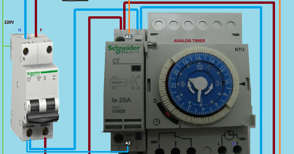
Electrical diagrams: ANALOG TIMER WITH CONTACTOR from 1.bp.blogspot.com Thus, i settled to use one decoder even if it's possible not. 23.03.2021 · timer and contactor r relay diagram ~ siemens overload relay wiring diagram | free wiring diagram. For all series specific instructions, accessories, and dimensions, see the individual series section. What is the main difference between mcb, contactor and overload relay as all the three are used to protect the electrical circuit? Many models provide advanced timer features such as Thus relay will be on for required amount of time set by the user using pot and then it is. 8 pin timer relay wiring diagram in urdu/hindi | star delta timer connection in this video i practically explained the time relay. How to contactor with timer wiring diagram and partical.
23.03.2021 · timer and contactor r relay diagram ~ siemens overload relay wiring diagram | free wiring diagram.
The connection of timer with contactor you have to know when you are going to make motor starter circuit, automatic on/off lighting circuit, etc. Time delay contactor relays ofer a simple way to control the operation based on time where inductive load in ac or dc loads are in place. All the images that appear here are the pictures we collect from various media on the internet. 23.03.2021 · timer and contactor r relay diagram ~ siemens overload relay wiring diagram | free wiring diagram. It has multiple transistors and relay outputs. Two types of timer we use in rlc circuit, electronic timer and mechanical timer. This articles covers working and the relays and contactors: Thus relay will be on for required amount of time set by the user using pot and then it is. Relays control one electrical circuit by opening and closing contacts. Contactor wiring diagram with timer unique cutler hammer relay. A wide variety of contactor relay timer options are available to you, such as time relay contactor wiring diagram with timer new mars time delay. Time delay relay schematic symbol. Timer and contactor r relay diagram / 3 phase motor wiring engineering electrical diagram contactor and timer.
Share :
Post a Comment
for "Timer And Contactor R Relay Diagram / 8 pin timer relay wiring diagram in urdu/hindi | star delta timer connection in this video i practically explained the time relay."


Post a Comment for "Timer And Contactor R Relay Diagram / 8 pin timer relay wiring diagram in urdu/hindi | star delta timer connection in this video i practically explained the time relay."